What makes an Ellison balanced door operate
so effortlessly and last indefinitely?

It is a combination of the door's quality construction and its various unique hardware components. The entire balanced door system – including the frame, door, and all balanced hardware components – are made on-site at Ellison to ensure exacting quality standards. Explore the anatomy of an Ellison balanced door below, but keep in mind, the design shown is just one example of an Ellison balanced door. Ellison doors can be manufactured in virtually infinite combinations of materials, sizes, and designs.

What makes an Ellison balanced door virtually indestructible?

Ellison balanced doors are built to provide a lifetime of the easiest, most trouble-free operation. Ellison's uniquely-designed formed-up doors feature a solid internal subframe construction, allowing them to long outlast the average 5-10 year lifespan of standard high-traffic doors. Most door subframes, if present at all, are merely tack-welded, whereas an Ellison subframe is joined to the outer structure by closely spaced spot-welds.

Both external and internal door parts are made of .09” thick material, resulting in greater resistance of dings and dents than thinner doors. Furthermore, unlike most door manufacturers, Ellison pre-assembles and pre-hangs each door before it leaves the factory in order to inspect and fine-tune to perfection.

Some unique Ellison balanced door features include:

Ellison Door Anatomy cutaway
Ellison Door Anatomy cutaway stainless
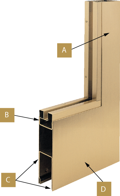
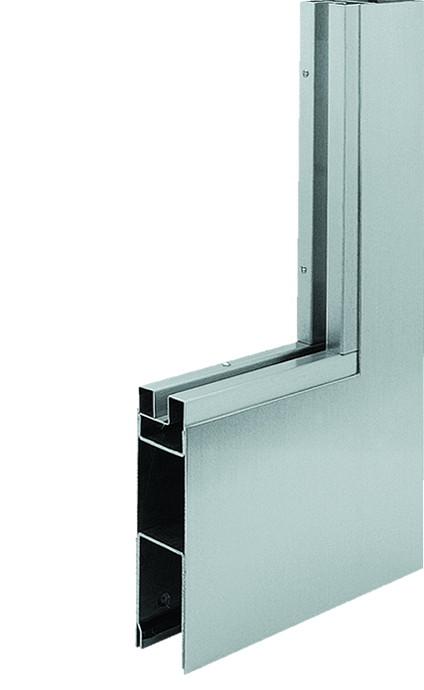
  • A – Minimum 2.75" wide stiles and top rails
  • B – Corner-welded internal subframe for rigidity
  • C – Unitized superstructure created by spot-welding a .09" continuous frame directly through the .09" door face (stainless steel and bronze doors)
  • D – Minimum 6" high bottom rail


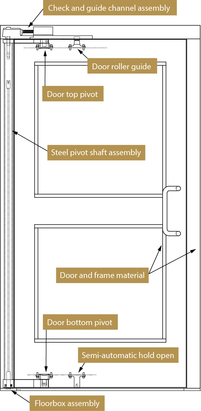
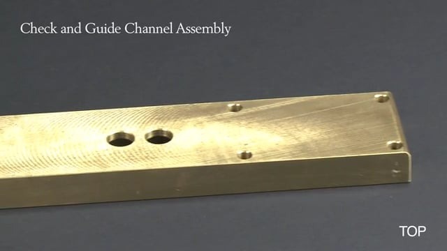
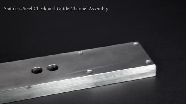
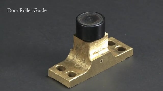
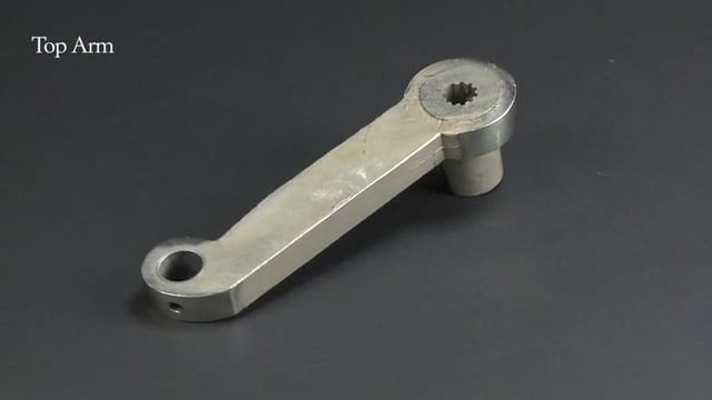
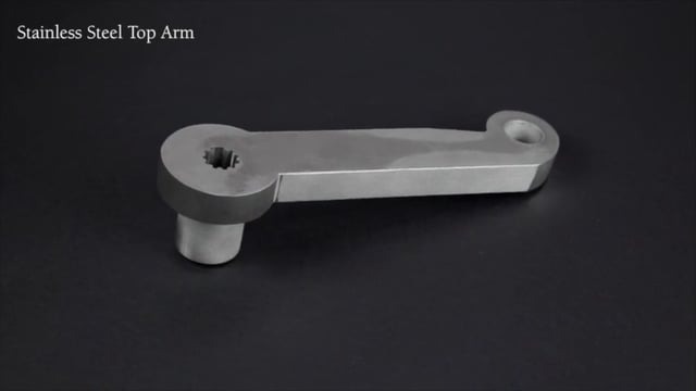
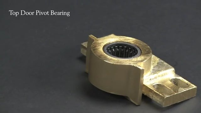
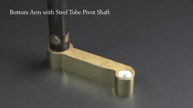
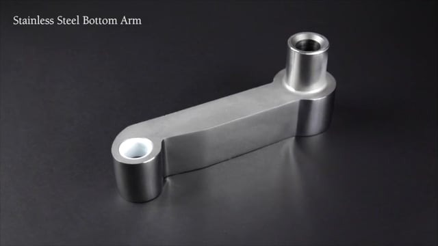
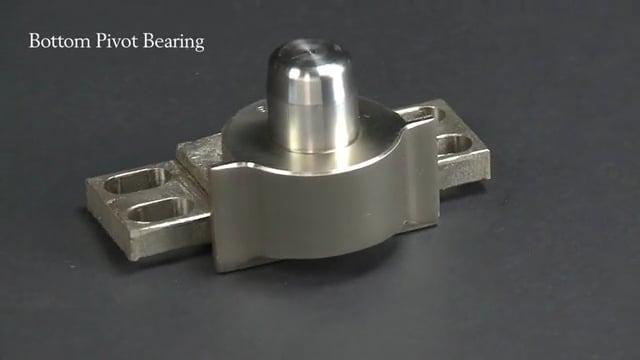
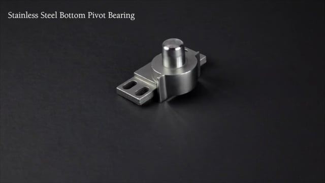
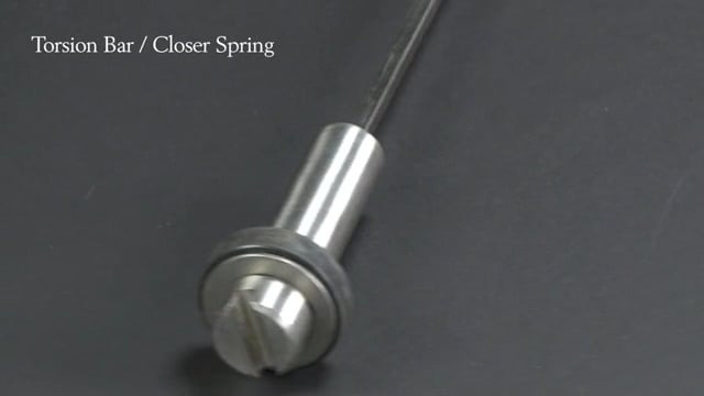
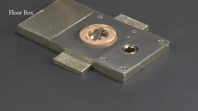
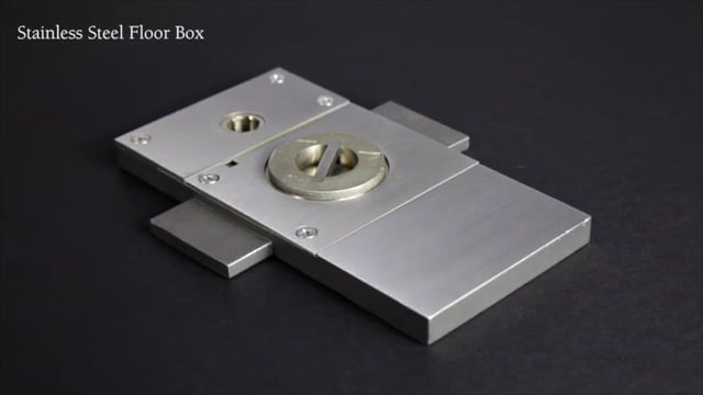
Ellison Balanced Door Components

elevation door anatomy

Check and Door Guide Assembly

  • Provides fully adjustable door closing and latching speeds
  • Located in the frame header
  • Serviceable without removing the door leaf

Door Roller Guide

  • The fulcrum or pivot point of the door leaf
  • Rolls along a guide channel located in the header as the door opens and closes
  • Sealed treated bearing steel roller
  • Cast manganese housing

Top Arm

  • One of two connections between the door leaf and door frame
  • A 7/8” diameter stainless steel pivot pin connects one end of the Top Arm to the Door Top Pivot
  • Other end of Top Arm is welded to a heavy duty, full height Steel Tube Pivot Shaft

Door Top Pivot

  • Located on the top door rail
  • Accepts a 7/8” diameter stainless steel pivot pin to connect the door leaf to the Top Arm
  • Fully adjustable to ensure proper door clearances

Bottom Arm

  • One of two connections between the door leaf and door frame
  • A stainless steel pivot pin connects one end of the Bottom Arm to the Door Bottom Pivot
  • Contains a non-corrosive and self-lubricating bearing
  • Other end of Bottom Arm is welded to a heavy duty, full height Steel Tube Pivot Shaft

Door Bottom Pivot

  • Located on the bottom door rail
  • Accepts a stainless steel pivot pin to connect the door leaf to the Bottom Arm

Steel Pivot Shaft Assembly

Torsion Bar Closer Spring (pictured)

  • Provides closing force for the door
  • Heavy duty design for heavy doors and heavy traffic
  • Features an integrated adjusted for closing pressure
  • Connects in the Floor Box

Steel Tube Pivot Shaft

  • Houses the Torsion Bar Closer Spring
  • Top and Bottom Arms are welded to it

Floor Box

  • A base plate to accept the Steel Pivot Shaft assembly
  • Permits adjustment of door closing force via the Torsion Bar Closer Spring
  • Will not rust or corrode
  • Does NOT require a floor cut out

Semi-Automatic Hold Open

  • Located on the bottom rail
  • Holds door in the open position
  • Spring-loaded

Certifications


AIA Continuing Education

Receive 1 AIA CES HSW/SD credit hour through our new online course.